MIL-DTL-3661D
4.6.8.1 Moving type contacts (not applicable to non-removable lens designs or to lamp housings with
integral resistor). The contact resistance of lampholders, indicator lights and indicator-light housings,
accommodating T-1-submidget flange base lamps, and T-1-3/4 midget flange base lamps, T-3-1/4 bayonet base
lamps and double contact candelabra base lamps, shall be tested in accordance with 4.6.8 and as follows:
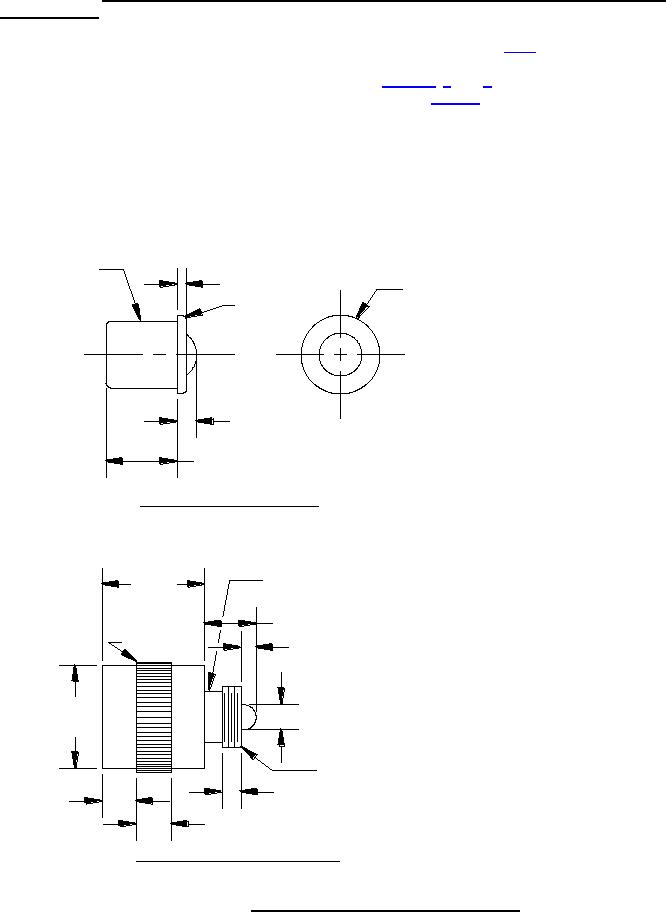
(a) Preparation for test - An applicable test plug (see figures 2, 3, and 4) shall be inserted into the lens or
socket of lampholder or indicator-light housing. If plug (figure 2) is inserted into the lens, the lens
shall then be tightened by hand in the indicator-light housing.
(b) Method of connection - Between two lamp terminals.
(c) Test current-0.1 ampere at 6 volts d.c. open circuit voltage.
(d) Number of lamp insertions-3.
(e) Number of measurements per insertion-one measurement. (The average of three readings shall be the
contact resistance).
Ø.248 ±.001
.030 ±.002
Ø.285 ±.002
R .020
+.000
.067 -.002
.260 ±.010
mm
INCHES
.001
0.03
MIDGET FLANGE TEST PLUG
.002
0.05
.010
0.25
.015
0.38
.020
0.51
.030
0.76
.055
1.40
.375
UNDERCUT BELOW
.066
1.68
±.015
THREAD ROOT DIAMETER
.067
1.70
.090
2.29
.183 ±.001
.125
3.18
KNURL
.183
4.65
.055 ±.010
.248
6.30
.260
6.60
.285
7.24
.375
9.53
Ø.375
Ø.090 ±.010
±.015
7/32 - 64 THD
.066 ±.010
.125 ±.015
NOTE: ALL DIMENSIONS IN INCHES
.125 ±.015
SUBMIDGET FLANGE TEST PLUG
FIGURE 2. Midget and submidget flange base test plugs.
18
For Parts Inquires call Parts Hangar, Inc (727) 493-0744
© Copyright 2015 Integrated Publishing, Inc.
A Service Disabled Veteran Owned Small Business