MIL-DTL-3661D
4.6.9.1 Flange base holders.
4.6.9.1.1 Midget flange base holders. For midget flange base holders, a test plug and test plug plunger (see
figure 6) shall be assembled (such that the shoulder of the plunger seats on the threaded end of the plug) and the test
plug shall be inserted to maximum engagement (minimum depressed position). The spring force shall then be
measured and shall be within the minimum spring pressure specified. The test plug plunger shall be depressed 0.032
+.002 and the spring force shall again be measured and shall not exceed the maximum spring pressure specified.
Lampholder springs shall then be subjected to a minimum of 500 cycles of operation from the minimum depressed
position to .032 .002 past the minimum depressed position. Following the 500 cycles, minimum spring force shall
again be measured and shall be as specified.
4.6.9.1.2 Submidget flange base holders. For submidget flange base holders, a test plug and test plug
plunger (see figure 6) shall be assembled (such that the shoulder of the plunger seats on the threaded end of the plug)
and the test plug shall be inserted to maximum engagement (minimum depressed position). The spring force shall
then be measured and shall be within the minimum spring pressure specified. The test plug plunger shall then be
depressed 0.030 .002 for incandescent bulb units; the spring force shall again be measured and shall not exceed the
maximum spring pressure specified. Lampholder springs shall then be subjected to a minimum of 500 cycles of
operation from the minimum depressed position to 0.030 .002 past the minimum depressed position. Following the
500 cycles, minimum spring force shall again be measured and shall be as specified.
4.6.9.2 Bayonet type holders. For bayonet base holders, the applicable test plug (figure 3 or 4), shall be
inserted but not locked in the lamp socket. A force shall then be applied gradually to the test plug until there is
sufficient pressure on the contact spring to permit the plug to be turned freely into the locking position. The contact
spring force shall be measured and be as specified. Remove the "J" locking pins from the applicable test plug
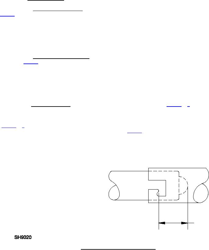
(figure 3 or 4), or make a duplicate plug without "J" pins. Insert the test plug to a depth of 0.255 inch for miniature,
or 0.316 inch for candelabra types below the hook in the "J" slot (see figure 7). Then withdraw the plug until the
contact reaches its fully extended positions. Repeat this operation a minimum of 500 cycles. At end of test, measure
the contact spring pressure and value shall be within the limits specified.
FOR MINIATURE BAYONET "D" = .255 INCH.
FOR CANDELABRA BAYONET "D" = .316 INCH
"D"
FIGURE 7. Bayonet base - "J" lock.ing engagement.
22
For Parts Inquires call Parts Hangar, Inc (727) 493-0744
© Copyright 2015 Integrated Publishing, Inc.
A Service Disabled Veteran Owned Small Business